
EVPN Overlay, L3VPN Data Center Interconnect
In the thick of studying for JNCIE-DC, I wanted to write a blog post on using L3VPN as a DCI technology, and running EVPN over the top. L3VPN and the IP/MPLS transport network is going to provide us with routing of the VTEP addresses that we can establish our EVPN/VXLAN overlay with. I think using L3VPN for DCI makes a lot of sense for a production network where the WAN may be managed my a separate team than the server/edge networking. To the team managing the EVPN/VXLAN overlay, all they care about is having L3 connectivity between VTEPs to establish VXLAN tunnels. To the WAN team, they can manage the IP/MPLS transport network and the MPLS VPN services the same way they probably always have, without any big WAN architectural changes.
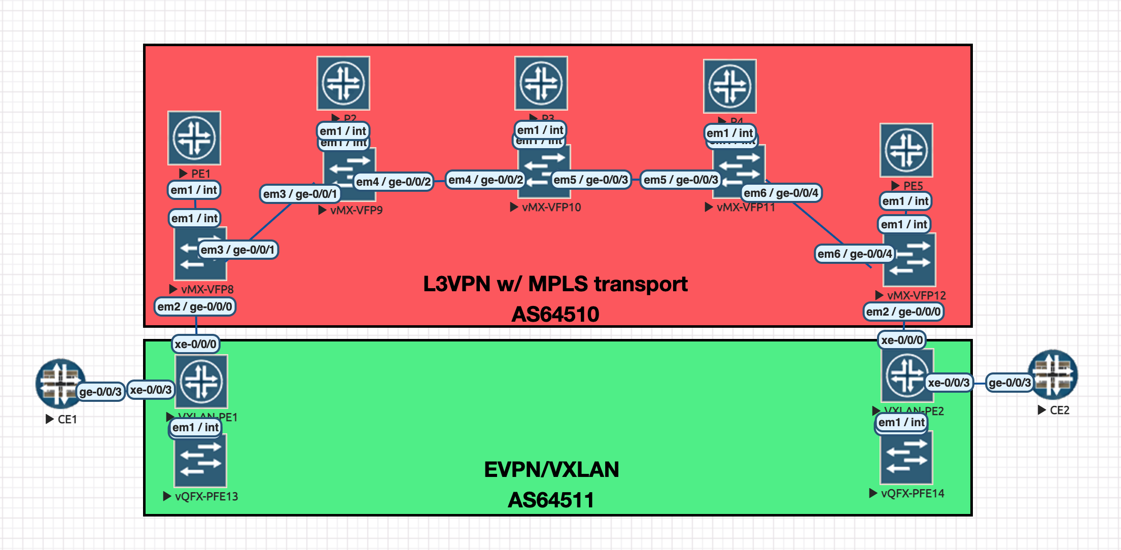
Topology (click picture to open in new tab)
Starting Point
- IS-IS Level 2, single area in AS64510
- RSVP/MPLS enabled interfaces
Establishing L3VPN WAN
We need to configure an MPLS LSP between PE1 and PE5 in AS64510 across our IP/MPLS Core. Then, we will configure BGP and the VRF needed for L3VPN DCI.
root@PE1# set protocols mpls lsp to-pe5 to 192.168.1.5

root@PE5# set protocols mpls lsp to-pe1 to 192.168.1.1

root@PE1# run show mpls lsp
Ingress LSP: 1 sessions
To              From            State Rt P     ActivePath       LSPname
192.168.1.5     192.168.1.1     Up     0 *                      to-pe5
Total 1 displayed, Up 1, Down 0

Egress LSP: 1 sessions
To              From            State   Rt Style Labelin Labelout LSPname
192.168.1.1     192.168.1.5     Up       0  1 FF       3        - to-pe1
PE1 BGP/VRF Config:
[edit]
+  routing-instances {
+      L3VPN-DCI {
+          instance-type vrf;
+          protocols {
+              bgp {
+                  group ce1 {
+                      type external;
+                      peer-as 64511;
+                      neighbor 192.168.100.1;
+                  }
+              }
+          }
+          interface ge-0/0/0.0;
+          route-distinguisher 192.168.1.1:100;
+          vrf-target target:100:100;
+      }
+  }
+  routing-options {
+      autonomous-system 64510;
+  }
[edit protocols]
+   bgp {
+       group ibgp {
+           type internal;
+           local-address 192.168.1.1;
+           family inet-vpn {
+               unicast;
+           }
+           neighbor 192.168.1.5;
+       }
+   }
PE5 BGP/VRF Config:
[edit]
+  routing-instances {
+      L3VPN-DCI {
+          instance-type vrf;
+          protocols {
+              bgp {
+                  group ce1 {
+                      type external;
+                      peer-as 64511;
+                      neighbor 192.168.200.1;
+                  }
+              }
+          }
+          interface ge-0/0/0.0;
+          route-distinguisher 192.168.1.5:100;
+          vrf-target target:100:100;
+      }
+  }
+  routing-options {
+      autonomous-system 64510;
+  }
[edit protocols]
+   bgp {
+       group ibgp {
+           type internal;
+           local-address 192.168.1.5;
+           family inet-vpn {
+               unicast;
+           }
+           neighbor 192.168.1.1;
+       }
+   }
On PE1:
root@PE1# run show route table L3VPN-DCI.inet.0

L3VPN-DCI.inet.0: 5 destinations, 5 routes (5 active, 0 holddown, 0 hidden)
+ = Active Route, - = Last Active, * = Both

1.1.1.1/32         *[BGP/170] 00:02:05, localpref 100
                      AS path: 64511 I, validation-state: unverified
                    >  to 192.168.100.1 via ge-0/0/0.0
2.2.2.2/32         *[BGP/170] 00:00:56, localpref 100, from 192.168.1.5
                      AS path: 64511 I, validation-state: unverified
                    >  to 100.64.0.1 via ge-0/0/1.0, label-switched-path to-pe5
192.168.100.0/31   *[Direct/0] 00:30:23
                    >  via ge-0/0/0.0
192.168.100.0/32   *[Local/0] 00:30:23
                       Local via ge-0/0/0.0
192.168.200.0/31   *[BGP/170] 00:00:58, localpref 100, from 192.168.1.5
                      AS path: I, validation-state: unverified
                    >  to 100.64.0.1 via ge-0/0/1.0, label-switched-path to-pe5

root@PE1# run show route advertising-protocol bgp 192.168.1.5

L3VPN-DCI.inet.0: 5 destinations, 5 routes (5 active, 0 holddown, 0 hidden)
  Prefix                  Nexthop              MED     Lclpref    AS path
* 1.1.1.1/32              Self                         100        64511 I
* 192.168.100.0/31        Self                         100        I
So far, so good. We are receiving routes from PE5 for this VRF and we are receiving local routes from VXLAN-PE1 and sending them to PE5. Let’s see if we are advertising 2.2.2.2/32 route from VXLAN-PE2 to VXLAN-PE1…
root@PE1# run show route advertising-protocol bgp 192.168.100.1

L3VPN-DCI.inet.0: 5 destinations, 5 routes (5 active, 0 holddown, 0 hidden)
  Prefix                  Nexthop              MED     Lclpref    AS path
* 192.168.200.0/31        Self                                    I
Oh no! We are only advertising the interface route from between VXLAN-PE2 and PE5.. How could this be? The Answer = AS Path Loop Detection
We are not advertising the 2.2.2.2/32 route with AS path 64511 to VXLAN-PE1.. because VXLAN-PE1 is of peer-as 64511. By default (without advertise-peer-as), we are not going to advertise routes containing a neighbor’s AS in path to that neighbor. We can work around this with “as-override”, which replaces the neighbor’s seen AS in the path with the PEs own AS, as such..
[edit routing-instances L3VPN-DCI protocols bgp group ce1]
+      as-override;

[edit]
root@PE1# commit
commit complete

[edit]
root@PE1# run show route advertising-protocol bgp 192.168.100.1

L3VPN-DCI.inet.0: 5 destinations, 5 routes (5 active, 0 holddown, 0 hidden)
  Prefix                  Nexthop              MED     Lclpref    AS path
* 2.2.2.2/32              Self                                    64510 I
* 192.168.200.0/31        Self                                    I
Much better, now we are advertising 2.2.2.2/32 successfully to our VXLAN-PE1. The same can be said for 1.1.1.1/32 to VXLAN-PE2.
Next up - EVPN/VXLAN
Now that we have connectivity between the loopbacks of each VXLAN-PE…
root@VXLAN-PE1# run ping 2.2.2.2
PING 2.2.2.2 (2.2.2.2): 56 data bytes
64 bytes from 2.2.2.2: icmp_seq=0 ttl=59 time=113.452 ms
^C
We can start configuring the overlay network, EVPN/VXLAN.
[edit interfaces xe-0/0/3]
+   unit 0 {
+       family ethernet-switching {
+           interface-mode trunk;
+           vlan {
+               members 123;
+           }
+       }
+   }
[edit routing-options]
+  router-id 1.1.1.1;
[edit protocols]
+   evpn {
+       vni-options {
+           vni 123 {
+               vrf-target target:123:123;
+           }
+       }
+       encapsulation vxlan;
+       extended-vni-list 123;
+   }
[edit]
+  switch-options {
+      vtep-source-interface lo0.0;
+      route-distinguisher 1.1.1.1:123;
+      vrf-target target:123:123;
+  }
[edit vlans]
+   vlan123 {
+       vlan-id 123;
+       vxlan {
+           vni 123;
+           ingress-node-replication;
+       }
+   }
and a similar configuration is not shown, but on VXLAN-PE2, obviously with a different source address on lo0.0 and route distinguisher value of 2.2.2.2:123
And pings from CE1->CE2 are successful
root@CE1# run ping 192.168.0.3
PING 192.168.0.3 (192.168.0.3): 56 data bytes
64 bytes from 192.168.0.3: icmp_seq=0 ttl=64 time=119.432 ms
64 bytes from 192.168.0.3: icmp_seq=1 ttl=64 time=120.514 ms
^C
Let’s check our L3/L2 tables end to end and see follow the traffic.
root@CE1# run show arp no-resolve
MAC Address       Address         Interface     Flags
50:01:00:10:00:03 192.168.0.3     ge-0/0/3.123         none

root@VXLAN-PE1# run show route table default-switch.evpn.0

default-switch.evpn.0: 4 destinations, 4 routes (4 active, 0 holddown, 0 hidden)
+ = Active Route, - = Last Active, * = Both

2:1.1.1.1:123::123::50:01:00:0f:00:03/304 MAC/IP
                   *[EVPN/170] 00:04:56
                      Indirect
2:2.2.2.2:123::123::50:01:00:10:00:03/304 MAC/IP
                   *[BGP/170] 00:02:16, localpref 100, from 2.2.2.2
                      AS path: I, validation-state: unverified
                    > to 192.168.100.0 via xe-0/0/0.0
3:1.1.1.1:123::123::1.1.1.1/248 IM
                   *[EVPN/170] 00:04:57
                      Indirect
3:2.2.2.2:123::123::2.2.2.2/248 IM
                   *[BGP/170] 00:02:18, localpref 100, from 2.2.2.2
                      AS path: I, validation-state: unverified
                    > to 192.168.100.0 via xe-0/0/0.0

root@VXLAN-PE1# run show ethernet-switching table brief

Ethernet switching table : 2 entries, 2 learned
Routing instance : default-switch
   Vlan                MAC                 MAC      Logical                Active
   name                address             flags    interface              source
   vlan123             50:01:00:0f:00:03   D        xe-0/0/3.0
   vlan123             50:01:00:10:00:03   D        vtep.32769             2.2.2.2
Very nice, we see our EVPN MAC/IP type 2 routes. We also see our autodiscovery type 1 routes. In the mac-table view of VXLAN-PE1, we can also see that 50:01:00:10:00:03 was learned (via EVPN route) sourced from vtep.32769 transport, our VXLAN tunnel to VXLAN-PE2.
Packet Capture VXLAN-PE1 -> PE1
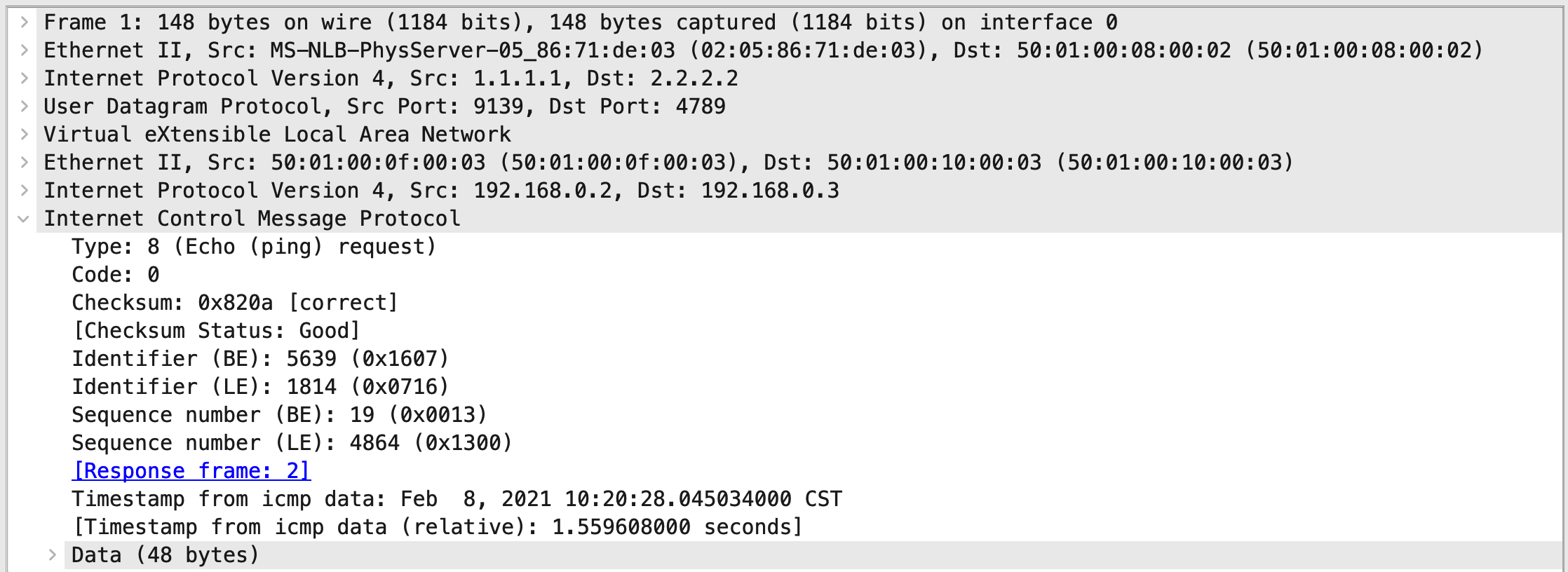 As stated earlier, from the perspective of VXLAN-PE1, it has no idea about the MPLS core to which VXLAN packets will travel. It just wraps up the ethernet payload in VXLAN and sends it.
Packet Capture PE1 -> MPLS Core
 And here we see our MPLS label stack toward the top, top label being for our RSVP-signaled LSP from PE1->PE2, and bottom label representing the L3VPN route toward VXLAN-PE2 for 2.2.2.2/32. Then, enclosed is our VXLAN and ethernet payload.
The End
In future posts, I hope to get more involved in EVPN as I keep studying for JNCIE-DC. This was just intriguing for me as it feels like a marriage between “traditional” Service Provider WAN and “modern” EVPN/VXLAN Overlay. I hope you enjoyed following along.
Configs
All configs are included here